


 45 / 66

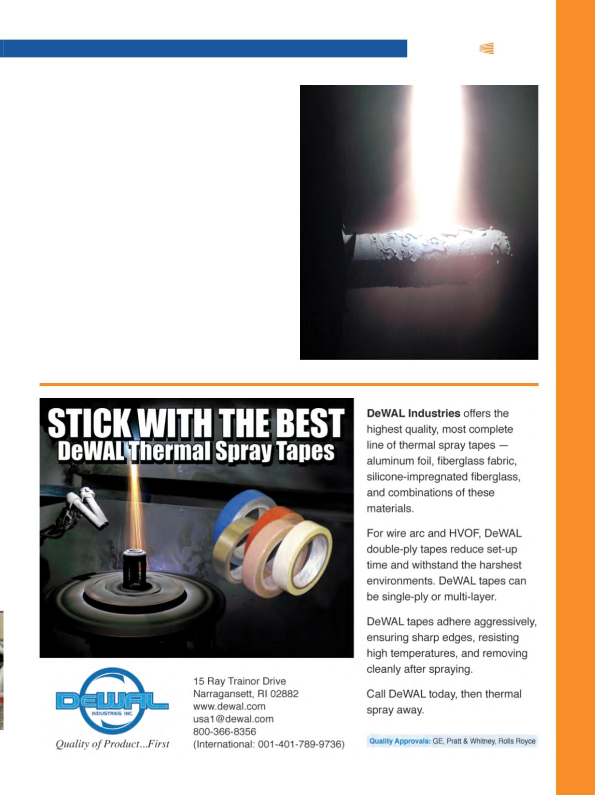
Fig. 4
— LPCS plasma plume (dummy part).
A range of coating operations and system configura-
tions are possible using low pressure and vacuum plasma
spray. Figure 1 illustrates a vacuum plasma spray process
during a batch operation where parts (ranging from IGT
turbine components to titanium implants) are coated us-
ing a vacuum rated turntable and robot system located in-
side the chamber.
With LPCS, continuous production is performed in con-
trast to a batch operation. This is common in high-volume
production sprayof thermal barrier coatings, suchasNiCrAlY
for aerospace turbine engine components. Figure 3 shows a
main process low pressure chamber located between two
load-locks, which enable part loading and unloading for
spraying coatings in the main chamber. The main process
chamber is able to maintain low pressure, while parts (e.g.,
turbine blades) are loaded into the load-locks and pumped
down to match the pressure of the process chamber for the
coating operation. Two work-piece manipulators (stings)
move parts into and out of the main process chamber and
manipulate components to be coated in the plasma process
stream. A gun drive (sting) further enables gun motion for
coating all desired surfaces of a component, in addition to
the two stings already mentioned. In LPCS, a higher-power
iTSSe
|
TSS
A D V A N C E D
M A T E R I A L S
&
P R O C E S S E S | F E B R U A R Y 2 0 1 5 |
i T S S e
9