


 57 / 74

heat-treating furnace, process require-
ments and operating conditions often
change, sometimes dramatically, and gas
measurement must remain accurate.
For a variable-area rotameter, if it is nec-
essary to know the proper flow rate, be
aware that a change in temperature,
pressure, or specific gravity of the gas
from that for which the meter was cali-
brated will cause a serious error in the
indicated scale reading. It is quite com-
mon in a heat treat shop to find flowme-
ters operating at pressures and temper-
atures different from those for which
they were calibrated.
Mass flowmeters
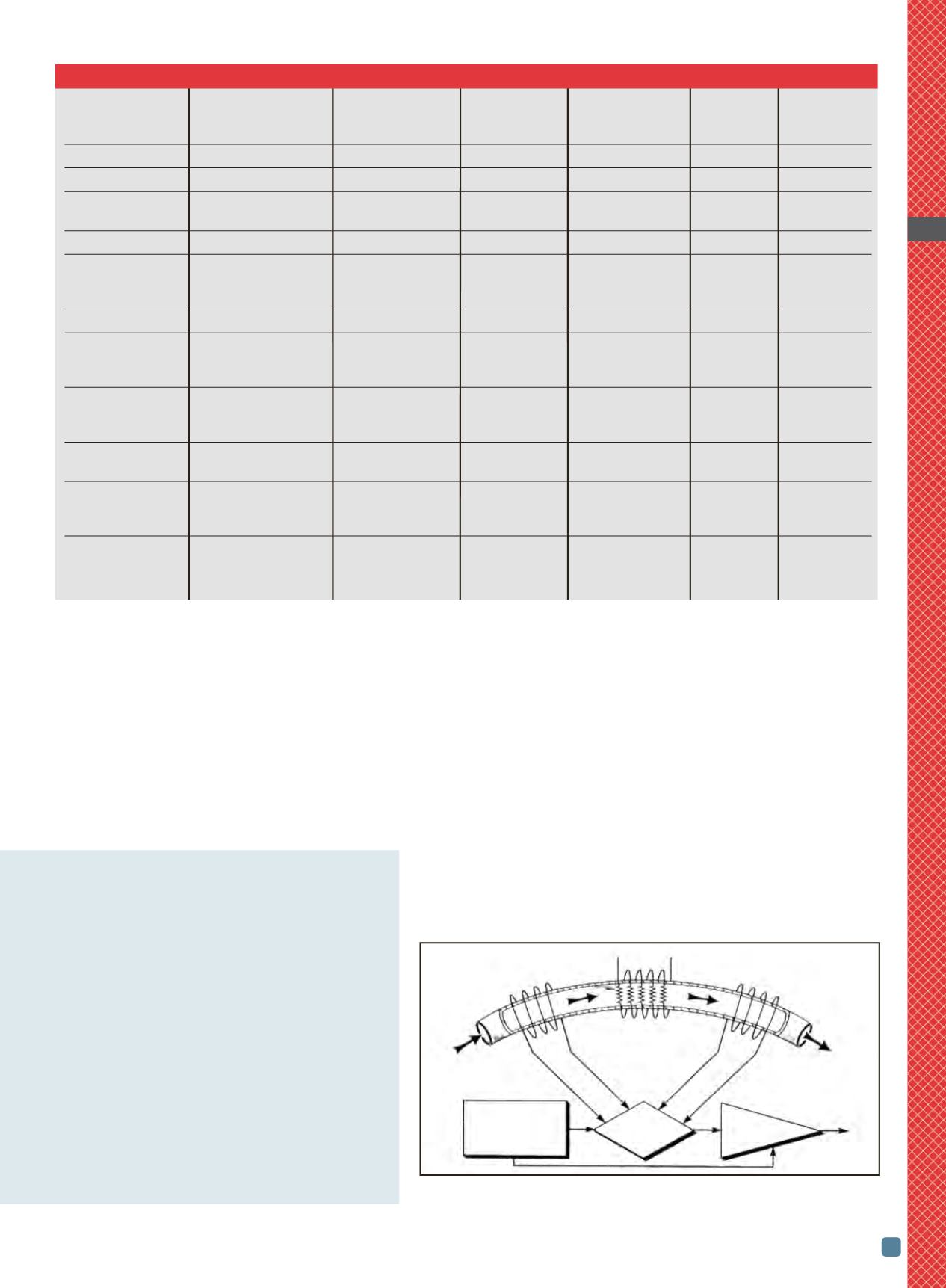
Thermal-mass flowmeters also are used
by heat treaters. In most industrial-grade
devices, gas enters the flow body and di-
vides into two flowpaths. Most of the flow
goes through the laminar-flow bypass,
creating a pressure drop that forces a
known fraction of the flow
through the sensor tube
(Fig. 1). A power supply is
used to direct a constant
amount of heat into the gas
stream. Resistance temperature-detector
(RTD) coils are placed around the bypass
sensor tube at its upstream and down-
stream ends. Heat is transferred to the
molecules of the flowing gas, independent
of pressure and temperature fluctuations.
The gas flow carries heat from the up-
stream coil to the downstream coil.
Therefore, the downstream coil has a
higher temperature and more resistance
than the upstream coil. The coils are legs
of a bridge circuit with the resultant out-
put voltage proportional to the differ-
ence between the coils’ resistance,
which, in turn, is proportional to the
mass flow rate. The two other parame-
57
ADVANCED MATERIALS & PROCESSES •
SEPTEMBER 2014
HTPRO
11
TABLE 1 — COMMONLY USED FLOW MEASUREMENT INSTRUMENTS BY FEATURE
Mechanical flow
Typical full-scale
Gas flow meter
Special installation reading level/
Electronic
accuracy, %
Typical
Pressure
type
requirements
scale type
flow reading of reading turndown
drop
Metal tube
Vertical mounting
Easy/linear
Available
3.5
3:1
Low
Metal cylinder tube Vertical mounting
Easy/linear
Available
1–2
25:1
Low
Glass or plastic
Vertical mounting
Easy/linear
No
1–2
10:1
Low
tube
Vane
None
Easy/linear
No
2–5
5:1
High/average
Moving orifice
Straight pipe
Complex/
Available
2–3
3:1–10:1 Low/average
upstream and
square root
downstream
Piston (with spring)
None
Easy/linear
No
1–5
5:1
Low/average
Orifice
Straight pipe
Hard/square root
Available
0.5–2
3:1–10:1
High
upstream and
downstream
Venturi
Straight pipe
Hard/square root
Available
0.5–2
3:1–10:1
Average
upstream and
downstream
Rotary impeller
None
Moderate/linear,
Available
0.5–2
10:1–20:1 Average
(Roots type)
total flow counter
Turbine
Straight pipe
Moderate/linear
Yes
0.5–3
10:1–20:1 Average
upstream and
downstream
Thermal mass
Straight pipe
Not applicable
Yes
1–2
10:1–100:1 Average/high
upstream and
downstream
as many of the gases involved are asphyxiants, as well
as being flammable, toxic, and possibly life threaten-
ing.
Also, electromagnetic flowmeters and all flow meas-
urement devices that use secondary instruments
such as pressure sensors to actuate a control valve or
send a signal to a remote source must be periodically
inspected, calibrated, repaired, and/or replaced. Im-
proper location of the flowmeter itself, the second-
ary sensor, or readout devices can result in
measurement errors and hidden costs.
Is it really necessary to learn about flowmeters
to be in control, stay in control, operate safely,
and keep operating costs as low as possible?
Simply stated, YES.
Fig. 1 —
Sensor tube measurement component of a thermal-mass flowmeter.
Courtesy of Omega Engineering Inc.
Power supply heater
T
1
, upstream
T
2
, downstream
temperature sensor temperature sensor
Bypass sensor tube
Flow
Linear
Bridge for output
Power supply
D
T
detection Amplifier