



 34 / 54

ADVANCED MATERIALS & PROCESSES •
FEBRUARY 2014
34
i
T
S
S
e
6
Accepted Practice to Test Bond
Strength of Thermal Spray Coatings
A
sufficient adhesion bond be-
tween the coating and substrate
is critical for the functionality of
the coated part. Coating integrity and
durability directly depends on the cohe-
sion bond strength. ASTM C633 “Stan-
dard Test Method for Adhesion or
Cohesion Strength of Thermal Spray
Coatings” is the baseline and mandatory
process to follow for tensile testing of
bond strength of thermal spray coatings.
The test is required as a condition of ap-
proval for new coatings and their suppli-
ers, and is the core qualification test for
coatings for aviation, oil and gas, auto-
motive, power, marine, and many other
industries. This practice clarifies details
of ASTM C633 requirements and provides examples of
best practices confirmed by hundreds of tests performed
wordwide, adopted by numerous industrial standards, and
requested to comply by international technical standardiza-
tion and certification organizations such as ISO, AS, SAE,
and Nadcap.
Test scope
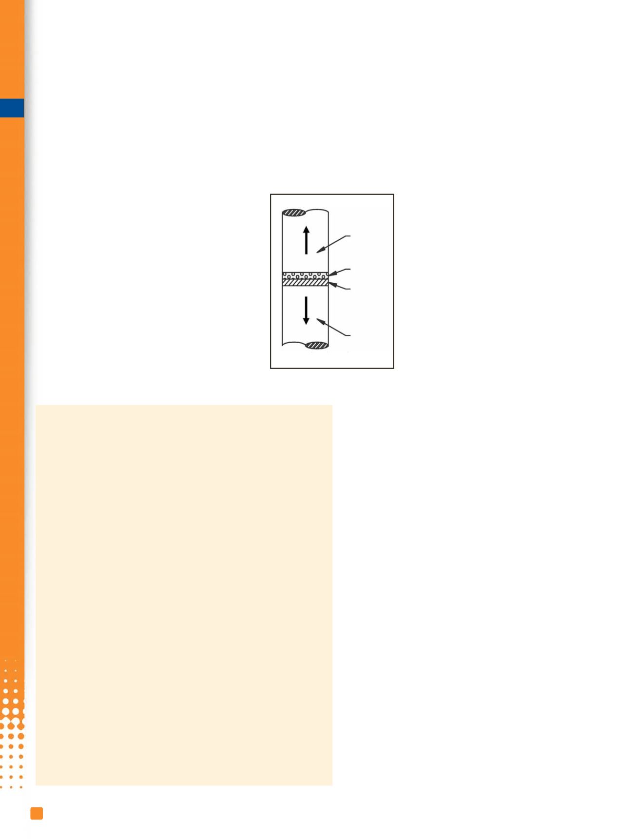
The ASTM C633 test applies tensile
stresses to coated systems consisting of a
coated sample glued to another cylindrical
sample as shown in Fig. 1. Alternatively, the
coating could be applied on a cylindrical
“button,” which is glued between two cylin-
drical samples as shown in Fig. 2. The load is
applied in a perpendicular direction to the in-
terface between the coating and substrate.
The amount of tensile load is gradually in-
creased from 0, which results in sample fail-
ure—the coating pulled out from the
substrate or fractured in two pieces inside the
coating. The coated surface is always a flat
circle with a diameter of 1 in. + 0/-0.005 in.,
and sample dimensions are standardized by
ASTM 633. Bond strength is calculated as the load at sam-
ple failure divided by the coating failure area.
Coating thickness
Coating thickness of 0.01 in. (0.25 mm) is recom-
mended if coating porosity is below 2%. If the coating has
high porosity, increase coating thickness to 0.015 in. (0.38
mm) and above, as recommended by ASTM C633 to pre-
vent glue penetration through the coating to the substrate,
but do not exceed the thickness required for the coated part
application. Thicker coatings have lower bond strength due
to residual stress accumulation that can lead to nonrepre-
sentative test results.
Coating thickness variation
The coating thickness should not vary across the surface
by more than 0.001 in. (0.025 mm). The coating surface
may be finished by grinding or machining when thickness
variation is excessive. Other treatment, such as grit blast-
ing, should not be used to level the coating thickness. Coat-
ing tapering increases sample misalignment, which results
in failure at a lower load.
Glue
Polyamide-epoxy FM 1000 Adhesive Film is recom-
mended (mandatory in many industrial specifications) as
a bonding glue for the coating tensile test. Advantages in-
clude allowing testing of high-porosity coatings (such as
abradable and ceramic coatings) without glue penetration
to the substrate. Disadvantages include losing its own
strength if stored at temperatures of 85°F (29°C) and
above, but can work for years if stored in a refrigerator.
The ASM Thermal Spray Society (TSS)
Accepted Practices Committee on
Metallography released a new document on
the accepted practice to test the bond
strength of thermal spray coatings.
Bond test step-by-step
• Inspect coating quality on bond caps. (Coating chipping, cracks,
delamination, separation, or overspray are not allowed.)
• Prepare mating caps; grit blast their flat surface. (Do not grit blast
coating surface).
• Apply a layer of glue on coating surface.
• Place coated samples with applied glue layer into V-groove of
curing fixture (see example of V-groove gravity fixture in Fig. 3).
• Add mating cap in the fixture with the grit-blasted surface facing the
glue layer on coated sample.
• Apply compression pressure to assembled samples. Note: Fig. 3
doesn’t show the additional weight on the top of assembled sample
to keep them in compression during glue curing (see below under
requirements).
• Place fixture with assembled and compressed samples in preheated
oven.
• Keep samples under pressure in heated oven until glue cures; cool
samples and release pressure.
• Carefully remove excess glue from each assembly with grinding.
Recommended abrasive size for grinding paper or wheel is not
coarser than 120 mesh; grinding direction is parallel to glued
surface; interface damage/removal of sample material(s) not allowed.
• Place assembled samples in grips of tensile machine, gradually apply
tensile load, and record failure load.
• Measure diameter (D) of sample failed face, and calculate the
failure area as follows: 3.14 × D
2
/4.
• Bond strength = load of failure/failure area.
To obtain representative results, compare properties of coatings de-
posited and tested at different facilities; test conditions and processes
require consistency and standardization.
Mating
cap
Adhesive
Coating
Bond cap
Fig. 1 —
Samples assembled
for bond test and applied tensile
load.