


 41 / 82

FEATURE ARTICLE
iTSSe
TSS
A D V A N C E D
M A T E R I A L S
&
P R O C E S S E S | F E B R U A R Y / M A R C H
2 0 1 7
4 1
9
iTSSe
TSS
BE imaging reveals atomic number contrast to illustrate coat-
ing phases. Spray angle and deposition efficiency effects are
analyzed using SEM microstructures of etched samples. For
example, nozzle erosion sometimes occurs during cold spray,
especially for hard materials such as MCrAlY or Inconel pow-
ders. The erodedmaterial could end up embedded in the coat-
ing and distinguished as an artifact.
SEM is used extensively to characterize coating chem-
istry via EDS. Figures 3 (a) to (d) show SEM micrographs of
IN625 feedstock powders and a cold spray coating, along with
the corresponding energy-dispersive x-ray analysis pattern
from the powder, and coating chemistry. Elemental mapping
is often done on powders prior to spray in order to evaluate
the level of segregation in the chemistry, as shown in Fig. 4
(a) to (d) on two types of MCrAlY powders. Coating porosity
characterization provides feedback to achieve optimum thick-
ness for a dense coating (Fig. 5) such as titanium. Coating po-
rosity evolution with different feedstock powders and powder
surface topography is also shown in Fig. 5.
Coating thickness and interface contour can be char-
acterized in a manner that makes SEM an indispensable and
versatile tool for evaluating coating integrity in the as-sprayed
condition, as well as in developing an understanding of bond-
ing to the substrate. Substrate hardness helps achieve good
coating deposition. Figures 6 (a) and (b) show the interface of a
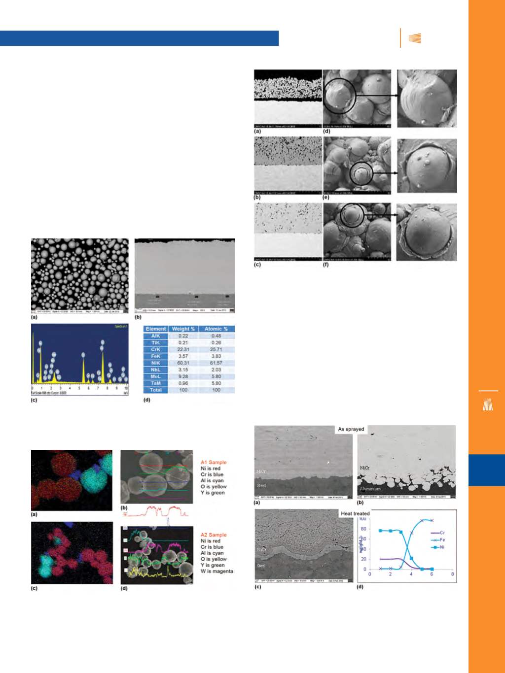
Fig. 3 —
SEMs show: (a) IN625 powder morphology and (b) as-
sprayed coating, and (c) energy-dispersive x-ray analysis pattern
and (d) listing of the elements from the spectrum in the coating.
Fig. 4 —
Energy-dispersive x-ray analysis mapping along with
SEMs taken from an MCrAlY cold spray coating illustrate elemental
segregation in the powders: (a, b) Powder type A and (c, d) Powder
type B.
Fig. 5 —
SEMs show powder morphology and cross-sectional
structure from two different feedstocks of WC-Co powder.
Fig. 6 —
SEMs from a NiCr cold spray coating (using helium gas)
on (a) AISI 4130 steel, (b) aluminum substrate, and (c) coating-sub-
strate interface after heat treatment, revealing an interdiffusion
zone; (d) composition across the interface taken by EDS.