
A D V A N C E D M A T E R I A L S & P R O C E S S E S | M A Y 2 0 1 6
3 0
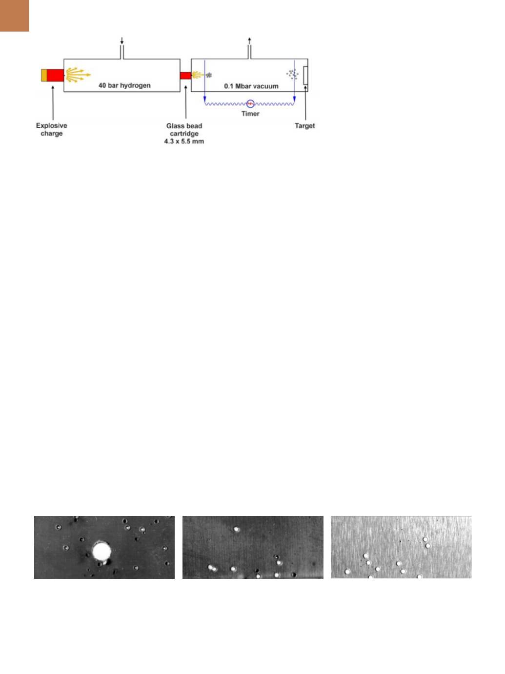
are held in position by a bursting disc
(Fig. 7).
In the first chamber, hydrogen
gas is compressed to 40 bar, while
the second chamber is evacuated to
0.1 Mbar. The target is mounted at the
end of the second chamber. Once the
pressure difference between the two
chambers is maximized, a shock wave
is sent into the compressed chamber
via a piston using a standard 12 bore
shotgun cartridge. This exceeds the
pressure specification of the bursting
disc and contents are fired through two
laser timing points into the target. In
this study, muzzle velocities reached
11,000 mph and a range of metal foils
were used as targets.
IMPACT RESULTS
Three different metal foils targets
were used, each featuring a 203
μ
m
thickness:
(a) Half hard 302 austenitic stainless
steel
(b)Annealed beryllium-copper alloy 25
(c) 2024T3 aluminum alloy
Figure 8 shows impact results for
the three materials using 177-
μ
m glass
microspheres travelling at 11,000 mph.
The dark microcraters show incom-
plete penetration, while those with
white centers show that the beads
have partially penetrated the metal.
The large hole in the stainless steel foil
was caused by a 1-mm ball bearing.
Note that the hole is perfectly round
because the speed was so high that the
metal did not have time to distort.
With regard to the stainless steel (a),
some
blind
microcraters are evident
where microspheres failed to pene-
trate, while other microcraters punc-
tured the foil. This could be due to
very small differences in the particle
size of the microspheres or an inho-
mogeneous structure in the stainless
steel. The annealed beryllium-copper
(b) showed similar results. In the case
of the aluminum alloy (c), however, all
the microspheres passed, showing less
resilience in the material to cosmic dust
impact.
CONCLUSION
By using glass microspheres to
model cosmic dust, it is possible to
simulate conditions found in space.
This enables aerospace engineers to be
more precise in specifying which mate-
rials should be used on the outside of
space vehicles, such as the Interna-
tional Space Station, in order to pro-
vide a safe work environment for the
astronauts.
Similarly, astronauts’ protective
suits, helmets, and visors were opti-
mized for safety by using the glass
microspheres and hypervelocity light
gas gun. The enhanced space apparel
now offers greater protection for astro-
nauts—even when they venture outside
the spacecraft to repair damage caused
by cosmic dust.
~AM&P
For more information:
Graham Ride-
al is CEO, Whitehouse Scientific Ltd.,
Whitchurch Rd., Waverton, Chester,
CH3 7PB, UK,
info@whitehousescientif- ic.com+44.0.1244.332626,
whitehouse- scientific.com.
Acknowledgment
The author thanks the team from
the University of Kent: Michael Baron,
who initiated the work; Mike Cole, who
operated the gun; and Mark Burchell for
inspiration.
Bibliography
1. M. Burchell, et al., Hypervelocity
Impact Studies Using the 2MV Van De
Graaff Accelerator and Two-Stage Light
Gas Gun of the University of Kent at
Canterbury,
Mea. Sci. Technol.,
V 10,
p 41-50, 1999.
2.
www.whitehousescientific.com.
3.
www.nist.gov.4. Image Analysis—Developing a
Robust Validation Procedure, pre-
sented by Graham Rideal at PARTEC,
Nuremberg, April 2016.
Fig. 7 —
Simplified schematic of hypervelocity gas gun.
Fig. 8 —
Impact results for 177-
μ
mglass microspheres travelling at 11,000mph. Half hard 302 austenitic stainless steel (a), annealed beryllium-
copper alloy 25 (b); 2024T3 aluminum alloy (c). Courtesy of M. Baron, University of Kent.
(a)
(b)
(c)


