


 23 / 74

A D V A N C E D
M A T E R I A L S
&
P R O C E S S E S |
S E P T E M B E R
2 0 1 5
2 3
observatories. With its 85-cm diameter,
bare polished primary mirror made of
HIP consolidated I-70 Be (I-70H), this
all-Be telescope operates at 5.5K. An
SEM and associated light micrograph
of I-70H are shown in Figs. 3 and 4. The
telescope shown in Fig. 5 is the proto-
type being tested at Jet Propulsion Lab-
oratory
[5]
. The excellent surface finish
and optical figure obtained, as well as
the insignificant thermal dimensional
instability observed when tested at 10K,
were a direct result of the improved
material quality achieved by the HIP
process. Because the optical figure of
the primary mirror was tested at cryo-
genic temperatures, the correction to
the small figure error was polished into
the surface in a process called cryo null
figuring. While neither the scatter nor
optical figure of this telescope would
be acceptable for a diffraction limited
visible wavelength system, it exceeded
specifications for the mid and far infra-
red wavelengths being observed.
The low oxide content and resid-
ual inhomogeneity found in I-70H (0.7%
BeO) needed to be reduced even fur-
ther before Be could become a viable
candidate for JWST mirrors, because
they operate at much shorter wave-
lengths. The next step—development
of spherical Be powder consolidated by
HIP—provided the ultimate material for
the JWST mirrors. Four mirrors are used
in the JWST, including the 18 segment
6.5-m primary, 738-mm secondary,
738 x 517-mm tertiary, and a 172.5-mm
fast steering mirror to stabilize the
image. All mirrors are gold-coated for
enhanced infrared reflectance. Figure 6
shows the finished mirrors and the com-
plete JWST
[6]
.
Each of the 18 primary mirror seg-
ments (plus spares) measures 1.3 m and
weighs approximately 40 kg (88 lb). Seg-
ments were polished to a surface figure
accuracy of 24.2 nm rms and include
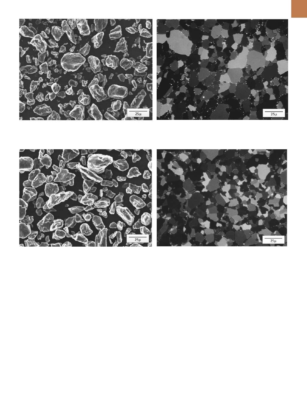
Fig. 1 —
500× SEM photomicrograph of S-200F grade blocky shaped
berylliumpowder produced by impact grinding. All images courtesy of
Materion except 5 and 6.
Fig. 2 —
Polarized light photomicrograph of S-200F grade beryllium.
Fig. 3 —
SEM photomicrograph of I-70 grade berylliumpowder pro-
duced to a higher purity in comparison to S-200F grade that improved
the ability to produce a polishedmirror surface. Powder is produced by
impact grinding.
Fig. 4 —
Polarized light photomicrograph of I-70H grade of beryllium
consolidated by HIP. Higher purity input powder in comparison to
S-200F is illustrated by fewer white oxide particles.