


 42 / 62

FEATURE
A D V A N C E D M A T E R I A L S & P R O C E S S E S | J U N E 2 0 1 5
4 2
10
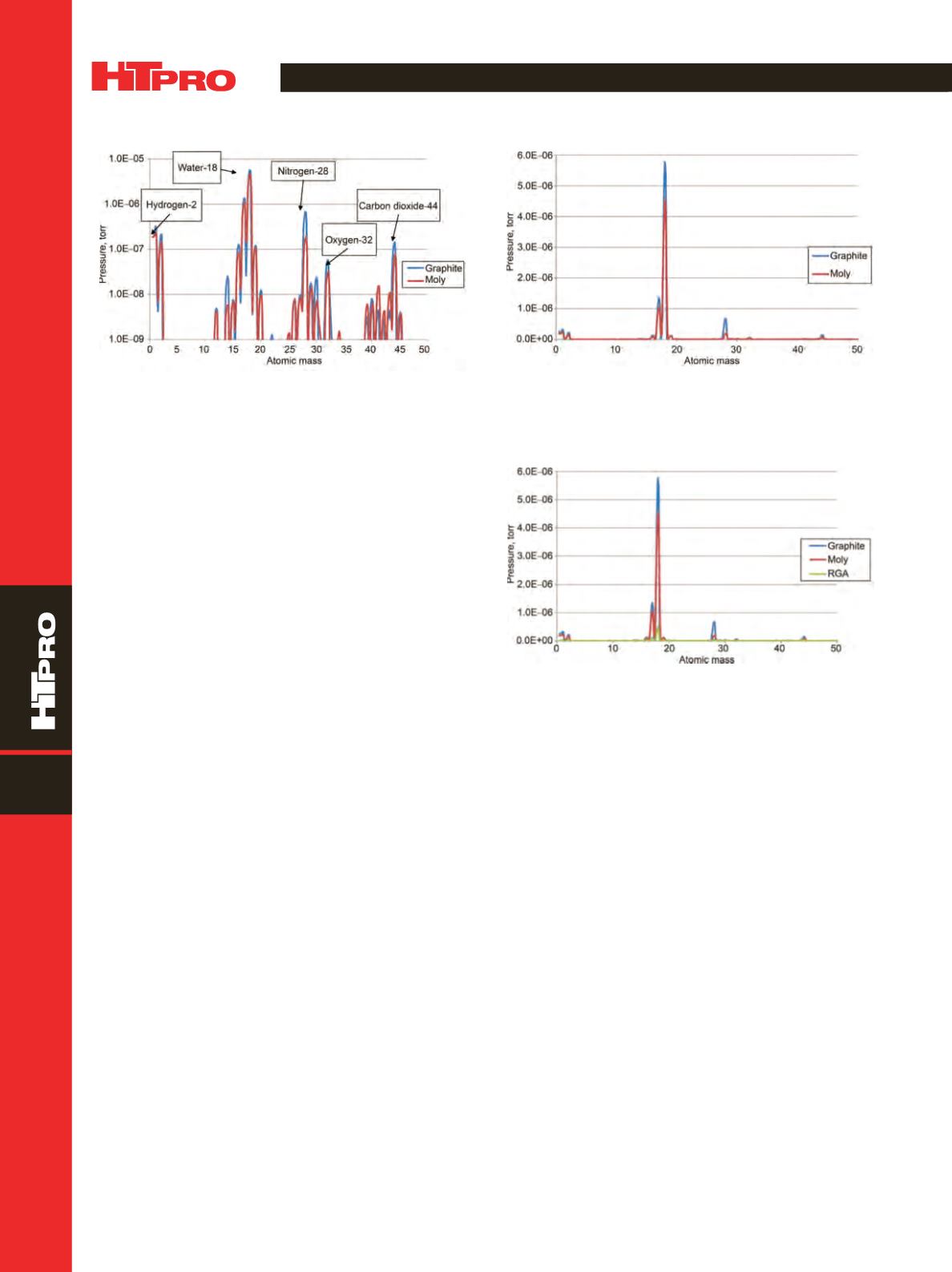
Fig. 8 —
Linear scale plot of residual gas analysis results in graph-
ite and all-metal (molybdenum) hot zones at ambient tempera-
ture and 5 x 10
−
5
torr.
Fig. 9 —
Linear scale plot of residual gas analysis results, includ-
ing traces of residual gases remaining in the residual gas analyzer
(RGA), for graphite and all-metal (molybdenum) hot zones at
ambient temperature and 5 x 10
−
5
torr.
all-metal design, and also to its retention of water vapor and
collection of air components when the furnace is open. In ad-
dition, the graphite carbon molecules contribute to the car-
bon dioxide residual gas. Figure 8 shows a linear RGA plot of
the above ambient temperature tests. Figure 9 includes trac-
es of residual gases that remained in the residual gas analyzer.
Residual gas trends with changes in vacuum and tem-
perature are shown in Fig. 10. Water, air, and carbon values
are higher in the graphite design.
Residual gases in the all-metal and graphite hot zones
when the furnaces are held at a temperature of 2200
°
F are
shown in Fig. 11. The graphite hot zone shows a signifi-
cantly larger number for water and air when held at this
temperature.
ANALYSIS OF RGA RESULTS
Results show that a molybdenum all-metal hot zone
should be used for processing materials that must meet crit-
ical surface contamination requirements. However, these
critical materials represent a very small portion (<10%) of all
the materials being processed in vacuum today.
To successfully minimize or eliminate surface contam-
ination in a furnace with a graphite hot zone, the following
conditions must apply:
•
Work must be clean
•
The furnace must have a proven low leak rate
•
The furnace must be able to achieve a low vacuum
initial pump down
•
The furnace must be baked out on a consistent
schedule to minimize internal contamination
Figure 12 shows an example of a critical material (tita-
nium bulkhead forgings) that can be processed in a graphite
hot zone furnace. A final acceptable surface condition can
be achieved in a graphite furnace that has been properly
prepared.
Fig. 7 —
Log scale plot of residual gas analysis results in graphite
and all-metal (molybdenum) hot zones at ambient temperature
and 5 x 10
−
5
torr.
Disadvantages of amolybdenumall-metal design com-
pared with a graphite design include:
•
Roughly 30% higher material cost than graphite
•
Less efficient and requires a larger, more expensive
power supply
•
About 50% lower projected service life
•
Embrittlement of the molybdenum as it ages (grain
growth)
•
Distortion including creep and buckling due to metal-
lization reactions
•
Difficult to repair compared with the graphite design
Differences in power requirements between molybde-
num and graphite hot zones are illustrated in Fig. 13, which
shows power consumedduringheatingof furnaces to2200
°
F
for the above test preparation and holding at temperature
for two hours. The graphite hot zone furnace is approxi-
mately 30% more efficient than the molybdenum hot zone
furnace, which represents a considerable savings on power
costs over the life of the hot zone.