


 48 / 66

ADVANCED MATERIALS & PROCESSES •
JUNE 2014
48
HTPRO
12
This is why it is necessary to size the ro-
tameter for each application. When
sized correctly, flow rate can be deter-
mined by matching the float position to
a calibrated scale on the outside of the
instrument. Many rotameters come
with a built-in valve to manually adjust
flow. Several shapes of floats are avail-
able for various applications.
Both glass and metal rotameters are
available. Glass and plastic rotameters
cost less and are more accurate than
metal tapered-tube rotameters (Fig. 3b),
but may not be able to provide the dura-
bility and reliability needed in a manufac-
turing environment. Metal rotameters
are reliable, but the machined tapered
tube limits the flow measurement range
(turndown). Another limitation is that
metal rotameters typically have brass or
aluminum bodies, which can make them
unsuitable for use in certain gases (am-
monia, for example).
Slotted-cylinder types
The flowmeter most commonly used in
the process industries substitutes a slot-
ted cylinder for the tapered tube (Fig.
3c). Compared with a metal rotameter,
a greater selection of construction ma-
terials and a flow turndown of at least
25:1 (vs. 3.6:1) are provided.
The lower portion of the float is a piston
that can “plug” the slot in the cylinder
wall. The float rises until enough of the
slot has opened to create equilibrium
between the two upward-acting flow
forces and the single downward-acting
force. As for rotameters, when in this
equilibrium position, float height is pro-
portional to flow rate. The basic equa-
tions for tapered tube and slotted
cylinder flowmeters are similar, with
their flowmeter coefficients (K factors)
accounting for any differences.
Flowmeter accessories
Regardless of the design of variable-area
flowmeters, flow measurement is taken
at some equilibrium point where the
fluid flow force is balanced by an oppos-
ing force exerted by a “flow element”
(such as a float). Either the force of grav-
ity or a spring is used to return the flow
element to its resting position when the
flow lessens. Gravity-operated flowme-
ters (Fig. 3a–c) must be installed in a
vertical position, while vane or spring-
operated devices (Fig. 3d–f ) can be
mounted in any position.
Some variable-area flowmeters can be
provided with position sensors and
transmitters (pneumatic, electronic, dig-
ital, and fiber optic) for connecting to re-
mote displays or controls. Most flowme-
ters have only flow alarm output signals,
although some provide a continuous sig-
nal that represents the flow rate.
A variable-area flowmeter or rotameter
is typically provided with calibration
data and a direct-reading scale for air or
water (or both). To size a meter for other
service, the actual flow must be con-
verted to a standard flow. Instrument
manufacturers use different standard
flow units. For liquids, the standard flow
is the water equivalent in gal/min at 70ºF
and 10 psi (20ºC, 69 kPa); for gases, it is
the air equivalent in standard cubic feet
per minute (scfm) at 70ºF and atmos-
pheric pressure. Tables listing standard
water and/or air equivalent values are
available from flowmeter manufactur-
ers, who also might provide slide rules,
nomographs, and computer software for
flowmeter sizing.
HTPRO
Look for Part 2 of this article in the Sep-
tember 2014 issue of HTPro covering se-
lection basics, sizing, mass flowmeter
overview, and FAQs about flowmeters.
For more information:
Daniel H. Herring
(The Heat Treat Doctor) is president,
The Herring Group Inc., P.O. Box 884,
Elmhurst, IL 60126-0884, 630.834.3017,
dhe r r i ng@he at- t re at- do c to r. com, heat-treat-doctor.com.
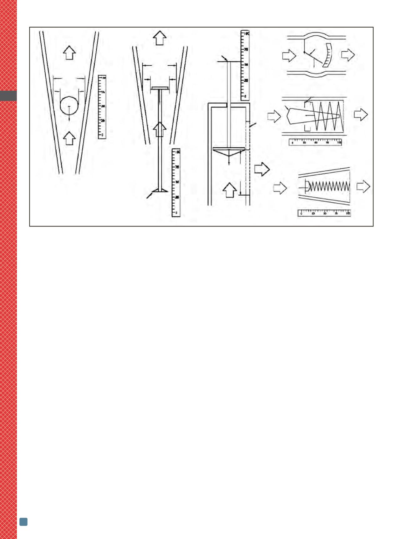
Fig. 3 —
Variable-area flowmeters: (a) glass/plastic tapered tube rotameter, (b) metal tapered tube rotameter, (c) slotted metal cylinder,
(d) vane type, (e) piston meter with spring-loaded orifice piston over a tapered plug, and (f) tapered tube with spring.
Flow
P
2
D Tube
D Float
g
P
1
Flow
(a)
Flow
P
2
D Tube
D Float
g
P
1
Flow
Indicator
(b)
Indicator
Slot
g P
2
Open
slot
length Flow
P
1
Flow
(c)
P
1
Vane P
2
Flow Flow
g
(d)
Moving orifice
Metering cone
P
1
P
2
F spring
Flow Flow
(e)
P
1
P
2
F spring
Flow Flow
(f)