


 50 / 102

A D V A N C E D M A T E R I A L S & P R O C E S S E S | O C T O B E R 2 0 1 5
5 0
10
FEATURE
REDUCING GEAR SIZE FOR COMPACT TRANSMISSION
DESIGN USING COMPUTER MODELING
Modeling shows that achieving required gear performance in a reduced gear size is possible
by changing the steel grade and heat treatment parameters during the design stage.
Zhichao (Charlie) Li,* B. Lynn Ferguson,* FASM, and Andrew Freborg,*
DANTE Solutions Inc., Cleveland
G
ears are themost important components in transmis-
sion and actuator designs. In many cases, transmis-
sion or actuator design must be reduced to achieve
weight or dimensional advantages without decreasing pow-
er density. One solution is to reduce gear size while keeping
the same output torque capacity. In general, gears used in
heavy load conditions are made of steel, and gear tooth re-
sidual surface stresses are critical to fatigue performance.
Compressive residual stresses in the critical region of a gear
improve its fatigue performance. However, many steel gears
are not processed to obtain residual surface compression, or
the benefit of residual compression is not considered in the
gear and transmission design.
Steel gears are heat treated to increase hardness and
strength for improved performance. Heat treatment intro-
duces compressive residual stresses in the gear surface,
which increases high-cycle fatigue performance
[1–2]
. Carbur-
ization and quench hardening generates compressive re-
sidual stresses in the gear surface due to delayed martens-
ite transformation with volume expansion. These stresses
reduce the magnitude of actual stresses generated in the
critical location of gears under service load. Computer mod-
eling is used to both troubleshoot and design heat treatment
processes for steel parts
[3–9]
. In this article, virtual computer
models using DANTE software are applied to help achieve
gear size reduction by including steel grade hardenability
and heat treatment in the design process.
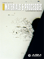
GEAR GEOMETRY
A CAD model of an AISI 4340 alloy steel spur gear with
16 straight teeth selected for this study is shown in Fig. 1.
Gear dimensions are 56 mm OD, 25 mm ID, 44 mm root di-
ameter, and 50 mm thick. Quench hardening in oil is used to
meet specified hardness and strength requirements.
The main concern for this gear is a failure at the gear
root fillet during a high cycle bending fatigue test. Previous
studies show that tangential stress at the root fillet under fa-
tigue load is the main driver of fatigue crack initiation and
propagation. Only one gear mid-plane cross section in the
axial direction is used in this study.
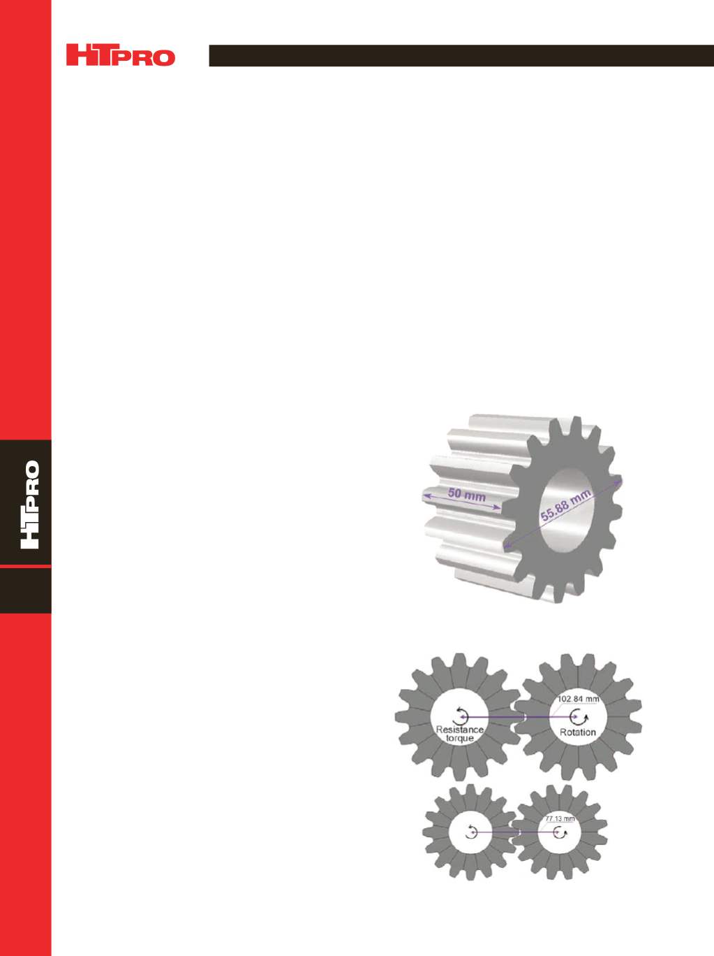
High cycle bending fatigue performance is used as
the main criterion to evaluate gear strength. To simplify the
study, it is assumed that the driver and driven gears are the
same size, and input and output torque (resistance) are the
same. Figure 2a shows the setup of the gear pair under bend-
ing due to rotational torque load for the original gear size de-
sign, with a centerline distance of 103mm. The driven gear is
on the left, with a 3287 N·m resistance torque load applied in
the direction as shown. A rotational displacement is applied
to the gear on the right. Input torque is also 3287 N·m.
DANTE was used to model the oil quench process for
the original 4340 steel gear and the magnitude of predicted
*Member of ASM International and ASM Heat Treating Society
Fig. 1 —
CADmodel and dimensions of original gear.
Fig. 2 —
Dynamic rotational bending model: (a) original gear size,
and (b) scaled reduced gear size.
(a)
(b)